


Calculate the SCFM.
SIRIUS Solid State Contactors
-
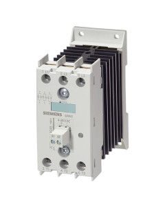
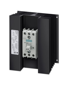 Siemens SIRIUS 3-Phase 600V 4-30VDC Input 50 Amp
Part #: 3RF2450-1AC45
-
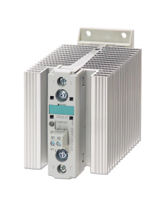
 Siemens SIRIUS 3-Phase 600V 4-30VDC Input 40 Amp
Part #: 3RF2440-1AC45
-
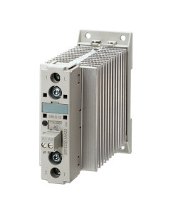
 Siemens SIRIUS 3-Phase 600V 4-30VDC Input 30 Amp
Part #: 3RF2430-1AC45
-
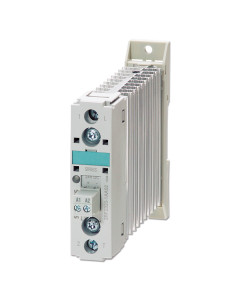
 Siemens SIRIUS 3-Phase 600V 4-30VDC Input 20 Amp
Part #: 3RF2420-1AC45
-
 Siemens SIRIUS 3-Phase 600V 4-30VDC Input 10 Amp
Part #: 3RF2410-1AC45
-
 Siemens SIRIUS 1-Phase 600V 4-30VDC Input 50 Amp
Part #: 3RF2350-1AA45
-
 Siemens SIRIUS 1-Phase 600V 4-30VDC Input 40 Amp
Part #: 3RF2340-1AA45
-
 Siemens SIRIUS 1-Phase 600V 4-30VDC Input 30 Amp
Part #: 3RF2330-1AA45
-
 Siemens SIRIUS 1-Phase 600V 4-30VDC Input 20 Amp
Part #: 3RF2320-1AA45
-
 Siemens SIRIUS 1-Phase 600V 4-30VDC Input 10 Amp
Part #: 3RF2310-1AA45
SIRIUS
Solid State Contactors
Single & Three Phase

Standards/Approvals: DIN EN 60947-4-3, UL508/CSA, CE

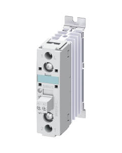
These complete units consist of a solid-state relay plus an optimized heat sink and are "ready to use." They offer defined rated currents to make selection as easy as possible.
Depending on the version, current strengths of up to 88 A are achieved. These contactors also offer all the special features of the solid-state relay, saving you time and money.
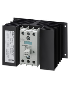
Contactors have an insulated mounting foot, making them easy to snap onto a standard mounting rail. They can also be mounted on support plates with fixing screws.
The insulation ensures they can be used in circuits with protective extra-low voltage (PELV) or safety extra-low voltage (SELV) in building management systems. For applications requiring extra personal safety, the heat sink can be grounded through a screw terminal.
3RF 23XX Solid State Contactors
1-Phase 600v 4-30VDC Input
10 A type current
Part #:

20 A type current
Part #:

30 A type current
Part #:

40 A type current
Part #:

50 A type current
Part #:

3RF 23XX Solid State Contactors
1-Phase 600v 4-30VDC Input
10 A type current

20 A type current

30 A type current

40 A type current

50 A type current

| PRODUCT # | ||||||
| GENERAL TECHNICAL DATA: | UNITS | |||||
| Product brand name | SIRIUS | SIRIUS | SIRIUS | SIRIUS | SIRIUS | |
|---|---|---|---|---|---|---|
| Product designation | Solid-state contactor |
Solid-state contactor |
Solid-state contactor |
Solid-state contactor |
Solid-state contactor |
|
| Product function | Zero-point switching |
Zero-point switching |
Zero-point switching |
Zero-point switching |
Zero-point switching |
|
| Number of poles / for main current circuit | 1 | 1 | 1 | 1 | 1 | |
| Protection class IP | IP20 | IP20 | IP20 | IP20 | IP20 | |
| Ambient temperature | ||||||
| • during operating | °C | -25 … +60 | -25 … +60 | -25 … +60 | -25 … +60 | -25 … +60 |
| • during storage | °C | -55 … +80 | -55 … +80 | -55 … +80 | -55 … +80 | -55 … +80 |
| Installation altitude / at height over sea level / maximum |
m | 1,000 | 1,000 | 1,000 | 1,000 | 1,000 |
| Resistance against vibration / according to IEC 60068-2-6 |
2g | 2g | 2g | 2g | 2g | |
| Resistance against shock / according to IEC 60068-2-27 |
15g / 11 ms | 15g / 11 ms | 15g / 11 ms | 15g / 11 ms | 15g / 11 ms | |
| Reference code | ||||||
| • according to DIN 40719 extended according to IEC 204-2 / according to IEC 752 |
K | K | K | K | K | |
| • according to DIN EN 61346-2 | Q | Q | Q | Q | Q | |
| Number of NC contacts / for auxiliary contacts |
0 | 0 | 0 | 0 | 0 | |
| Number of NO contacts / for auxiliary contacts |
0 | 0 | 0 | 0 | 0 | |
| Number of changeover contacts / for auxiliary contacts |
0 | 0 | 0 | 0 | 0 | |
| MAIN CIRCUIT: | ||||||
| Number of NO contacts / for main contacts | 1 | 1 | 1 | 1 | 1 | |
| Number of NC contacts / for main contacts | 0 | 0 | 0 | 0 | 0 | |
| Operating Current | ||||||
| • at AC-1 / at 400 V / rated value | A | 10.5 | 20 | 30 | 40 | 50 |
| • at AC-51 / rated value | A | 10.5 | 20 | 30 | 40 | 50 |
| Operating current / minimum | mA | 100 | 500 | 500 | 500 | 500 |
| Operating voltage | ||||||
| • at 50 Hz / at AC / rated value | V | 48 … 600 | 48 … 600 | 48 … 600 | 48 … 600 | 48 … 600 |
| • at 60 Hz / at AC / rated value | V | 48 … 600 | 48 … 600 | 48 … 600 | 48 … 600 | 48 … 600 |
| Working range relative to the operating voltage |
||||||
| • at 50 Hz / with AC | V | 40 … 660 | 40 … 660 | 40 … 660 | 40 … 660 | 40 … 660 |
| • at 60 Hz / with AC | V | 40 … 660 | 40 … 660 | 40 … 660 | 40 … 660 | 40 … 660 |
| Operating frequency | ||||||
| • rated value | Hz | 50 … 60 | 50 … 60 | 50 … 60 | 50 … 60 | 50 … 60 |
| Insulation voltage / rated value | V | 600 | 600 | 600 | 600 | 600 |
| Voltage slew rate / at the thyristor / for main contacts / maximum permissible |
V/µs | 500 | 1000 | 1000 | 1000 | 1000 |
| Block voltage / at the thyristor / for main contacts / maximum permissible |
V | 1,200 | 1,200 | 1,200 | 1,200 | 1,200 |
| Reverse current / of the thyristor | mA | 10 | 10 | 10 | 10 | 10 |
| Derating temperature | °C | 40 | 40 | 40 | 40 | 40 |
| Active power loss / total / typical | W | 11 | 20 | 33 | 44 | 54 |
| Resistance against the impulse current / rated value |
A | 200 | 600 | 600 | 1,200 | 1,150 |
| I2t-level / maximum | A²·s | 200 | 1,800 | 1,800 | 7,200 | 6,600 |
| CONTROL CIRCUIT/CONTROL: | ||||||
| Voltage type / of control feed voltage | DC | DC | DC | DC | DC | |
| Control supply voltage / 1 | ||||||
| • for DC | ||||||
| • initial rated value | V | 4 | 4 | 4 | 4 | 4 |
| • final rated value | V | 30 | 30 | 30 | 30 | 30 |
| Control supply voltage | ||||||
| • for DC / final value for signal<0>-recognition |
V | 1 | 1 | 1 | 1 | 1 |
| Control current | ||||||
| • for DC / rated value | mA | 20 | 20 | 20 | 20 | 20 |
| INSTALLATION/MOUNTING/ DIMENSIONS: | ||||||
| Mounting type | Screw and snap-on mounting onto 35mm standard mounting rail | |||||
| Mounting type / series installation | Yes | Yes | Yes | Yes | Yes | |
| Design of the thread / of the screw for fastening of the operating resource |
M4 | M4 | M4 | M4 | M4 | |
| Tightening torque / of the screw for fastening of the operating resource |
N·m | 1.5 | 1.5 | 1.5 | 1.5 | 1.5 |
| Width | mm | 22.5 | 22.5 | 45 | 67.5 | 67.5 |
| Height | mm | 100 | 100 | 100 | 100 | 100 |
| Depth | mm | 94 | 140.5 | 140.5 | 156 | 156 |
| CONNECTIONS/TERMINALS: | ||||||
| Design of the electrical connection / for the main current circuit |
screw-type terminals |
screw-type terminals |
screw-type terminals |
screw-type terminals |
screw-type terminals |
|
| Design of the thread / of the connection screw / for main contacts |
M4 | M4 | M4 | M4 | M4 | |
| Tightening torque / for main contacts | ||||||
| • with screw-type terminals | N·m | 2 … 2.5 | 2 … 2.5 | 2 … 2.5 | 2 … 2.5 | 2 … 2.5 |
| Tightening torque (lbf-in) / for main contacts | ||||||
| • with screw-type terminals | lbf·in | 18 … 22 | 18 … 22 | 18 … 22 | 18 … 22 | 18 … 22 |
| Type of the connectable conductor cross-section |
||||||
| • for main contacts | ||||||
| • solid | 2x (1.5 … 2.5 mm²), 2x (2.5 … 6 mm²) |
2x (1.5 … 2.5 mm²), 2x (2.5 … 6 mm²) |
2x (1.5 … 2.5 mm²), 2x (2.5 … 6 mm²) |
2x (1.5 … 2.5 mm²), 2x (2.5 … 6 mm²) |
2x (1.5 … 2.5 mm²), 2x (2.5 … 6 mm²) |
|
| • finely stranded | ||||||
| • w/ conductor end processing | 2x (1 … 2.5 mm²), 2x (2.5 … 6 mm²), 1x 10 mm² |
2x (1 … 2.5 mm²), 2x (2.5 … 6 mm²), 1x 10 mm² |
2x (1 … 2.5 mm²), 2x (2.5 … 6 mm²), 1x 10 mm² |
2x (1 … 2.5 mm²), 2x (2.5 … 6 mm²), 1x 10 mm² |
2x (1 … 2.5 mm²), 2x (2.5 … 6 mm²), 1x 10 mm² |
|
| • for AWG conductors | ||||||
| • for main contacts | 2x (14 … 10) | 2x (18 … 14) | 2x (14 … 10) | 2x (14 … 10) | 2x (14 … 10) | |
| • for auxiliary and control contacts | 1x (AWG 20 … 12) | 1x (AWG 20 … 12) | 1x (AWG 20 … 12) | 1x (AWG 20 … 12) | 1x (AWG 20 … 12) | |
| • for auxiliary and control contacts | ||||||
| • solid | 1x (0.5 … 2.5 mm²), 2x (0.5 … 1.0 mm²) |
1x (0.5 … 2.5 mm²), 2x (0.5 … 1.0 mm²) |
1x (0.5 … 2.5 mm²), 2x (0.5 … 1.0 mm²) |
1x (0.5 … 2.5 mm²), 2x (0.5 … 1.0 mm²) |
1x (0.5 … 2.5 mm²), 2x (0.5 … 1.0 mm²) |
|
| • finely stranded | ||||||
| • w/ conductor end processing | 1x (0.5 … 2.5 mm²), 2x (0.5 … 1.0 mm²) |
1x (0.5 … 2.5 mm²), 2x (0.5 … 1.0 mm²) |
1x (0.5 … 2.5 mm²), 2x (0.5 … 1.0 mm²) |
1x (0.5 … 2.5 mm²), 2x (0.5 … 1.0 mm²) |
1x (0.5 … 2.5 mm²), 2x (0.5 … 1.0 mm²) |
|
| • w/out conductor final cutting | 1x (0.5 … 2.5 mm²), 2x (0.5 … 1.0 mm²) |
1x (0.5 … 2.5 mm²), 2x (0.5 … 1.0 mm²) |
1x (0.5 … 2.5 mm²), 2x (0.5 … 1.0 mm²) |
1x (0.5 … 2.5 mm²), 2x (0.5 … 1.0 mm²) |
1x (0.5 … 2.5 mm²), 2x (0.5 … 1.0 mm²) |
|
| Conductor cross section that can be connected |
||||||
| • for main contacts | ||||||
| • single- or multi-stranded | mm² | 1.5 … 6 | 1.5 … 6 | 1.5 … 6 | 1.5 … 6 | 1.5 … 6 |
| • stranded wire | ||||||
| • w/ conductor end processing | mm² | 1 … 10 | 1 … 10 | 1 … 10 | 1 … 10 | 1 … 10 |
| • for auxiliary and control contacts | ||||||
| • solid | mm² | 0.5 … 2.5 | 0.5 … 2.5 | 0.5 … 2.5 | 0.5 … 2.5 | 0.5 … 2.5 |
| • stranded wire | ||||||
| • w/ conductor end processing | mm² | 0.5 … 2.5 | 0.5 … 2.5 | 0.5 … 2.5 | 0.5 … 2.5 | 0.5 … 2.5 |
| • w/out conductor final cutting | mm² | 0.5 … 2.5 | 0.5 … 2.5 | 0.5 … 2.5 | 0.5 … 2.5 | 0.5 … 2.5 |
| AWG number / as coded connectable conductor cross section / for main contacts |
14 … 10 | 14 … 10 | 14 … 10 | 14 … 10 | 14 … 10 | |
| Design of the electrical connection / for auxiliary and control current circuit |
screw-type terminals |
screw-type terminals |
screw-type terminals |
screw-type terminals |
screw-type terminals |
|
| Design of the thread / of the connection screw / of the auxiliary and control pins |
M3 | M3 | M3 | M3 | M3 | |
| AWG number / as coded connectable conductor cross section |
||||||
| • for auxiliary and control contacts | 20 … 12 | 20 … 12 | 20 … 12 | 20 … 12 | 20 … 12 | |
| Skinning length / of the cable / for main contacts |
mm | 7 | 7 | 7 | 7 | 7 |
| Skinning length / of the cable / for auxiliary and control contacts |
mm | 7 | 7 | 7 | 7 | 7 |
| Tightening torque / for auxiliary and control contacts | ||||||
| • with screw-type terminals | N·m | 0.5 … 0.6 | 0.5 … 0.6 | 0.5 … 0.6 | 0.5 … 0.6 | 0.5 … 0.6 |
| Tightening torque (lbf-in) / for auxillary and control contacts |
||||||
| • with screw-type terminals | lbf·in | 4.5 … 5.3 | 4.5 … 5.3 | 4.5 … 5.3 | 4.5 … 5.3 | 4.5 … 5.3 |
| CERTIFICATES/APPROVALS: | ||||||
| General Product Approval | EMC | Declaration of Conformity | ||||


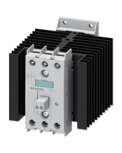
The complete units consist of a solid-state relay plus optimized heat sink, and are therefore "ready to use". They offer defined rated currents to make selection as easy as possible. Depending on the version, current strengths of up to 88 A are achieved. It also offers all the special features of the solid-state relay with regard to saving time and money.
With their insulated mounting foot they can easily be snapped onto a standard mounting rail, or they can be mounted on support plates with fixing screws. This insulation enables them to be used in circuits with protective extra-low voltage (PELV) or safety extra-low voltage (SELV) in building management systems. For other applications, such as for extended personal safety, the heat sink can be grounded through a screw terminal.
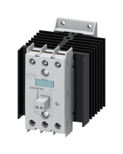
3RF 24XX Solid State Contactors
3-Phase 600v 4-30VDC Input
10 A type current
Part #:

20 A type current
Part #:

30 A type current
Part #:

40 A type current
Part #:

50 A type current
Part #:

10 A type current

20 A type current

30 A type current

40 A type current

50 A type current

| PRODUCT # | ||||||
| GENERAL TECHNICAL DATA: | UNITS | |||||
|---|---|---|---|---|---|---|
| Product brand name | SIRIUS Solid-state |
SIRIUS Solid-state |
SIRIUS Solid-state |
SIRIUS Solid-state |
SIRIUS Solid-state |
|
| Product designation | contactor | contactor | contactor | contactor | contactor | |
| Product function | Zero-point switching |
Zero-point switching |
Zero-point switching |
Zero-point switching |
Zero-point switching |
|
| Number of poles / for main current circuit | 3 | 3 | 3 | 3 | 3 | |
| Protection class IP | IP20 | IP20 | IP20 | IP20 | IP20 | |
| Ambient temperature | ||||||
| • during operating | °C | -25 … +60 | -25 … +60 | -25 … +60 | -25 … +60 | -25 … +60 |
| • during storage | °C | -55 … +80 | -55 … +80 | -55 … +80 | -55 … +80 | -55 … +80 |
| Installation altitude / at height over sea level / maximum |
m | 1,000 | 1,000 | 1,000 | 1,000 | 1,000 |
| Resistance against vibration / according to IEC 60068-2-6 |
2g | 2g | 2g | 2g | 2g | |
| Resistance against shock / according to IEC 60068-2-27 |
15g / 11 ms | 15g / 11 ms | 15g / 11 ms | 15g / 11 ms | 15g / 11 ms | |
| Reference code | ||||||
| • according to DIN 40719 extended according to IEC 204-2 / according to IEC 752 |
K | K | K | K | K | |
| • according to DIN EN 61346-2 | Q | Q | Q | Q | Q | |
| Number of NC contacts / for auxiliary contacts |
0 | 0 | 0 | 0 | 0 | |
| Number of NO contacts / for auxiliary contacts |
0 | 0 | 0 | 0 | 0 | |
| Number of changeover contacts / for auxiliary contacts |
0 | 0 | 0 | 0 | 0 | |
| MAIN CIRCUIT: | ||||||
| Number of NO contacts / for main contacts | 3 | 3 | 3 | 3 | 3 | |
| Number of NC contacts / for main contacts | 0 | 0 | 0 | 0 | 0 | |
| Operating Current | ||||||
| • at AC-1 / at 400 V / rated value | A | 10 | 20 | 30 | 40 | 50 |
| • at AC-51 / rated value | A | 10 | 20 | 30 | 40 | 50 |
| Operating current / minimum | mA | 500 | 500 | 500 | 500 | 500 |
| Operating voltage | ||||||
| • at 50 Hz / at AC / rated value | V | 48 … 600 | 48 … 600 | 48 … 600 | 48 … 600 | 48 … 600 |
| • at 60 Hz / at AC / rated value | V | 48 … 600 | 48 … 600 | 48 … 600 | 48 … 600 | 48 … 600 |
| Working range relative to the operating voltage |
||||||
| • at 50 Hz / with AC | V | 40 … 660 | 40 … 660 | 40 … 660 | 40 … 660 | 40 … 660 |
| • at 60 Hz / with AC | V | 40 … 660 | 40 … 660 | 40 … 660 | 40 … 660 | 40 … 660 |
| Operating frequency | ||||||
| • rated value | Hz | 50 … 60 | 50 … 60 | 50 … 60 | 50 … 60 | 50 … 60 |
| Insulation voltage / rated value | V | 600 | 600 | 600 | 600 | 600 |
| Voltage slew rate / at the thyristor / for main contacts / maximum permissible |
V/µs | 500 | 1000 | 1000 | 1000 | 1000 |
| Block voltage / at the thyristor / for main contacts / maximum permissible |
V | 1,200 | 1,200 | 1,200 | 1,600 | 1,600 |
| Reverse current / of the thyristor | mA | 10 | 10 | 10 | 10 | 10 |
| Derating temperature | °C | 40 | 40 | 40 | 40 | 40 |
| Relative symmetrical tolerance / of the operation frequency |
% | 10 | 10 | 10 | 10 | 10 |
| Resistance against the impulse current / rated value |
A | 300 | 600 | 1,200 | 1,150 | 1,150 |
| I2t-level / maximum | A²·s | 450 | 1,800 | 7,200 | 6,600 | 6,600 |
| CONTROL CIRCUIT/CONTROL: | ||||||
| Voltage type / of control feed voltage | DC | DC | DC | DC | DC | |
| Control supply voltage / 1 | ||||||
| • for DC | V | 4 … 30 | 4 … 30 | 4 … 30 | 4 … 30 | 4 … 30 |
| Control supply voltage | ||||||
| • for DC / final value for signal<0>-recognition |
V | 1 | 1 | 1 | 1 | 1 |
| Tolerance of the line frequency | Hz | 5 | 5 | 5 | 5 | 5 |
| Control current | ||||||
| • at minimum control supply voltage / for DC |
mA | 2 | 2 | 2 | 2 | 2 |
| • for DC / rated value | mA | 30 | 30 | 30 | 30 | 30 |
| INSTALLATION/MOUNTING/ DIMENSIONS: | ||||||
| Mounting type | Screw & snap-on mounting onto 35mm standard mounting rail |
Screw Fixing | Screw Fixing | Screw Fixing | ||
| Mounting type / series installation | Yes | Yes | Yes | Yes | Yes | |
| Design of the thread / of the screw for fastening of the operating resource |
M4 | M4 | M4 | M4 | M4 | |
| Tightening torque / of the screw for fastening of the operating resource |
N·m | 1.5 | 1.5 | 1.5 | 1.5 | 1.5 |
| Width | mm | 45 | 90 | 113.5 | 157.5 | 157.5 |
| Height | mm | 100 | 100 | 100 | 100 | 180 |
| Depth | mm | 104.5 | 112.5 | 121 | 121 | 121 |
| CONNECTIONS/TERMINALS: | ||||||
| Design of the electrical connection / for the main current circuit |
screw-type terminals |
screw-type terminals |
screw-type terminals |
screw-type terminals |
screw-type terminals |
|
| Design of the thread / of the connection screw / for main contacts |
M4 | M4 | M4 | M4 | M4 | |
| Tightening torque / for main contacts | ||||||
| • with screw-type terminals | N·m | 2 … 2.5 | 2 … 2.5 | 2 … 2.5 | 2 … 2.5 | 2 … 2.5 |
| Tightening torque (lbf-in) / for main contacts | ||||||
| • with screw-type terminals | lbf·in | 18 … 22 | 18 … 22 | 18 … 22 | 18 … 22 | 18 … 22 |
| Type of the connectable conductor cross-section |
||||||
| • for main contacts | ||||||
| • solid | 2x (1.5 … 2.5 mm²), 2x (2.5 … 6 mm²) |
2x (0.5 … 2.5 mm² ) | 2x (1.5 … 2.5 mm_), 2x (2.5 … 6 mm_) |
2x (1.5 … 2.5 mm²), 2x (2.5 … 6 mm²) |
2x (1.5 … 2.5 mm²), 2x (2.5 … 6 mm²) |
|
| • finely stranded | ||||||
| • w/ conductor end processing | 2x (1 … 2.5 mm²), 2x (2.5 … 6 mm²), 1x 10 mm² |
2x (0.5 … 1.5 mm²) | 2x (1 … 2.5 mm_), 2x (2.5 … 6 mm_), 1x 10 mm_ |
2x (1 … 2.5 mm²), 2x (2.5 … 6 mm²), 1x 10 mm² |
2x (1 … 2.5 mm²), 2x (2.5 … 6 mm²), 1x 10 mm² |
|
| • for AWG conductors | ||||||
| • for main contacts | 2x (14 … 10) | 2x (18 … 14) | 2x (14 … 10) | 2x (14 … 10) | 2x (14 … 10) | |
| • for auxiliary and control contacts | 1x (AWG 20 … 12) | 1x (AWG 20 … 12) | 1x (AWG 20 … 12) | 1x (AWG 20 … 12) | 1x (AWG 20 … 12) | |
| • for auxiliary and control contacts | ||||||
| • solid | 1x (0.5 … 2.5 mm²), 2x (0.5 … 1.0 mm²) |
1x (0.5 … 2.5 mm²), 2x (0.5 … 1.0 mm²) |
1x (0.5 … 2.5 mm²), 2x (0.5 … 1.0 mm²) |
1x (0.5 … 2.5 mm²), 2x (0.5 … 1.0 mm²) |
1x (0.5 … 2.5 mm²), 2x (0.5 … 1.0 mm²) |
|
| • finely stranded | ||||||
| • w/ conductor end processing | 1x (0.5 … 2.5 mm²), 2x (0.5 … 1.0 mm²) |
1x (0.5 … 2.5 mm²), 2x (0.5 … 1.0 mm²) |
1x (0.5 … 2.5 mm²), 2x (0.5 … 1.0 mm²) |
1x (0.5 … 2.5 mm²), 2x (0.5 … 1.0 mm²) |
1x (0.5 … 2.5 mm²), 2x (0.5 … 1.0 mm²) |
|
| • w/out conductor final cutting | 1x (0.5 … 2.5 mm²), 2x (0.5 … 1.0 mm²) |
1x (0.5 … 2.5 mm²), 2x (0.5 … 1.0 mm²) |
1x (0.5 … 2.5 mm²), 2x (0.5 … 1.0 mm²) |
1x (0.5 … 2.5 mm²), 2x (0.5 … 1.0 mm²) |
1x (0.5 … 2.5 mm²), 2x (0.5 … 1.0 mm²) |
|
| Conductor cross section that can be connected |
||||||
| • for main contacts | ||||||
| • single- or multi-stranded | mm² | 1.5 … 6 | 0.5 … 2.5 | 1.5 … 6 | 1.5 … 6 | 1.5 … 6 |
| • stranded wire | ||||||
| • w/ conductor end processing | mm² | 1 … 10 | 0.5 … 1.5 | 1 … 10 | 1 … 10 | 1 … 10 |
| • for auxiliary and control contacts | ||||||
| • solid | mm² | 0.5 … 2.5 | 0.5 … 2.5 | 0.5 … 2.5 | 0.5 … 2.5 | 0.5 … 2.5 |
| • stranded wire | ||||||
| • w/ conductor end processing | mm² | 0.5 … 2.5 | 0.5 … 2.5 | 0.5 … 2.5 | 0.5 … 2.5 | 0.5 … 2.5 |
| • w/out conductor final cutting | mm² | 0.5 … 2.5 | 0.5 … 2.5 | 0.5 … 2.5 | 0.5 … 2.5 | 0.5 … 2.5 |
| AWG number / as coded connectable conductor cross section / for main contacts |
14 … 10 | 14 … 10 | 14 … 10 | 14 … 10 | 14 … 10 | |
| Design of the electrical connection / for auxiliary and control current circuit |
screw-type terminals |
screw-type terminals |
screw-type terminals |
screw-type terminals |
screw-type terminals |
|
| Design of the thread / of the connection screw / of the auxiliary and control pins |
M3 | M3 | M3 | M3 | M3 | |
| AWG number / as coded connectable conductor cross section |
||||||
| • for auxiliary and control contacts | 20 … 12 | 20 … 12 | 20 … 12 | 20 … 12 | 20 … 12 | |
| Skinning length / of the cable / for main contacts |
mm | 7 | 7 | 7 | 7 | 7 |
| Skinning length / of the cable / for auxiliary and control contacts |
mm | 7 | 7 | 7 | 7 | 7 |
| Tightening torque / for auxiliary and control contacts | ||||||
| • with screw-type terminals | N·m | 0.5 … 0.6 | 0.5 … 0.6 | 0.5 … 0.6 | 0.5 … 0.6 | 0.5 … 0.6 |
| Tightening torque (lbf-in) / for auxillary and control contacts |
||||||
| • with screw-type terminals | lbf·in | 7.5 … 5.3 | 7.5 … 5.3 | 7.5 … 5.3 | 7.5 … 5.3 | 7.5 … 5.3 |
| CERTIFICATES/APPROVALS | ||||||
| General Product Approval | EMC | Declaration of Conformity | ||||

